
Some of the older engine durability test cells at Navistar needed their fuel consumption measurement system updated. The existing one was built on a dedicated IC board and finding replacement components was becoming increasingly difficult. More importantly, a newer system that was capable of interfacing with other test cell software was also a necessity.
When it comes to automating a measurement system, in addition to the automation of the measurement process itself, two other important tasks have to be kept in mind and automated as well, if possible: the task of checking if the measurement accuracy is within a given specification, and the task of calibrating the system if it is out of spec. These three automation components (the process itself, accuracy checks, and calibration) can be applied to a large group of measurement systems and industrial processes. The fuel flow measurement system belongs to this group.
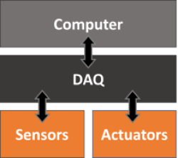
With that in mind, the fuel flow measurement system consists of two physical parts: a fuel column located in the test cell and a calibration cart. The former performs the measurement task, while the latter the check and calibration tasks. If we remember the post DAQ, SBC, etc., in this particular case, a computer and a DAQ device were used to automate the system. The computer was a very capable test cell PC, that was in charge of controlling many of test cell sub-systems, being the fuel flow measurement system one of them. A single DAQ device (LabJack U6) was part of the test cell hardware and interfaced with the sensors and actuators of both the fuel column and the calibration cart. Below are the main requirements of the automation system:
- Real-time 10 Hz monitoring of fuel flow (or consumption by the engine)
- Automatic fuel column refill
- Capability of manual measurements taken by the operator
- Capability of measurements commanded by other software via UDP/IP
- Automated fuel column calibration (fuel mass as a function of voltage)
- Automated fuel column periodic flow accuracy check
- Automatic report generation for calibrations and flow checks
Fuel Column

As the engine draws fuel from the column, the output current of the pressure transducer (measured as a voltage over a resistor) is processed by the automation software and a real-time fuel flow value is displayed in the graphical user interface. When the fuel level drops below a certain voltage threshold, the software operates the refill solenoid, topping off the column. This process repeats itself automatically so there’s always fuel in the column.
When a measurement is triggered, either manually or through an external software request, the fuel column is topped off first and then the fuel flow is measured and averaged for a user-defined time duration. The final value is displayed on the interface and sent to the software that made the request, if that’s the case.
An analog input port on the LabJack U6 acquires the voltage signal from the pressure transducer after it’s filtered with an anti-aliasing low-pass filter. The 110 V refill solenoid is switched on or off via a solid-state relay connected to one of the LabJack’s analog output ports.
Calibration Cart
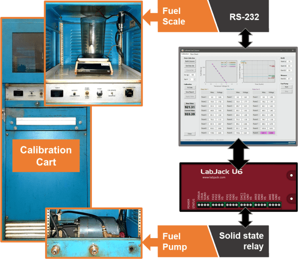
The cart is used to characterize the relationship between the fuel mass in the column and the voltage output from the pressure transducer located at its bottom. When the column is connected to the fuel cart for a calibration procedure, a fuel pump on the cart draws fuel from the column into a container sitting on a high precision scale inside the cart. The automation software executes this procedure automatically by drawing incremental amounts of fuel. At each increment, the fuel mass value is measured by the scale. A function is then fitted to the collected data points of mass vs. voltage.
When the cart is being used to check an existing calibration, the flow measured by the automation software is compared to the fuel flow calculated by using the actual mass collected inside the container on top of the high precision scale, over a certain amount of time.
An analog output port on the LabJack U6 is used to turn the cart pump on or off through a solid-state relay. Communication between the automation software and the fuel scale is done using a RS-232 serial cable connected directly to the test cell PC where the software is installed.
Reporting

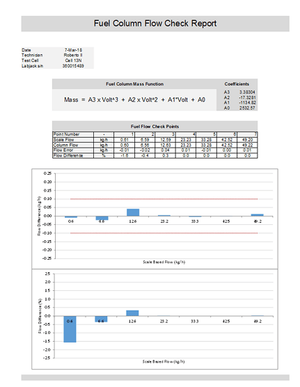
Keeping track of calibrations and flow checks is critical for the engine lab compliance with quality norms and, generally speaking, is an important part of an automated system. To that end, Excel-based reports are automatically generated for each calibration procedure or flow check. These are stored in a database and can be later retrieved and analyzed.
Fuel Column Simulator
Finally, because engine test cells are running most of the time, it was difficult to find a window of opportunity to develop the automation software that controls the fuel column.
To work around this limitation, a fuel column simulator that also includes the calibration cart functionality was created.
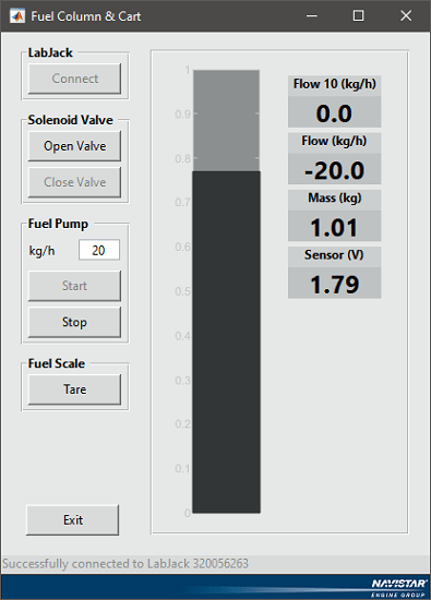
The filling and emptying behavior of the column, as well as the other automation system components, was closely matched in the simulator. The main ones were:
- refill solenoid valve on/off
- calibration cart pump on/off
- fuel scale serial communication
- fuel scale tare operation
Summary
The main idea of this post was to show a real application of the concepts of data acquisition and automation using a computer and a DAQ device. All the elements presented here can be applied to a wide variety of systems. While this one wasn’t too complex, it was part of a larger project to fully automate an engine test cell. Nonetheless, even more complex automation projects can usually be broken down into smaller, more manageable pieces. And that’s how you go about it.

Hello Raj! Yep. I had to code one to capture the fuel column functionality. Especially for the I/O interfaces.