
An H-bridge is an electronic circuit that can switch the polarity of the voltage applied to a load. In our case the load is an electric DC motor that is capable of rotating forward and backward. By using a PWM as an input to the system defined by the H-bridge and the motor, we can go from the digital to the analog domain, similarly to what we did with the Raspberry Pi DAC. In this case however, the motor replaces the RC filter and the output is a continuous motor torque/speed instead of a voltage value.
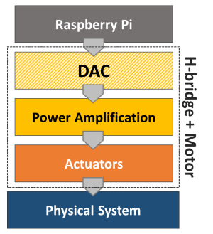
Looking at the bottom half of the diagram introduced in Analog-to-Digital Conversion, the power amplification stage is integrated into the H-bridge and the actuator is the motor. Together they constitute a digital-to-analog converter in a broader sense.
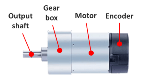
Since the Pi has a limited power output capability, the amplification stage is achieved with an external power supply or a set of batteries that can produce both the higher voltage and current required by a DC motor application. For this post, I’ll use a variable DC power supply set to 12 V and a small DC motor with an integrated encoder. While the encoder won’t be required at this point, it will be used in future posts. And last but not least, there’s the H-bridge, which can be in a single IC chip or part of an IC board. The two types will be considered for some Python code running on a Raspberry Pi 4B.
SN754410 quadruple half-H driver (chip)
The Texas Instruments SN754410 can be used as 4 half-H drivers or 2 H-bridge drivers, depending on the input configuration. The latter can be used to independently control two DC motors with forward and backward rotation. The figure below shows the pins on the chip and the corresponding GPIO pins on the Raspberry Pi.
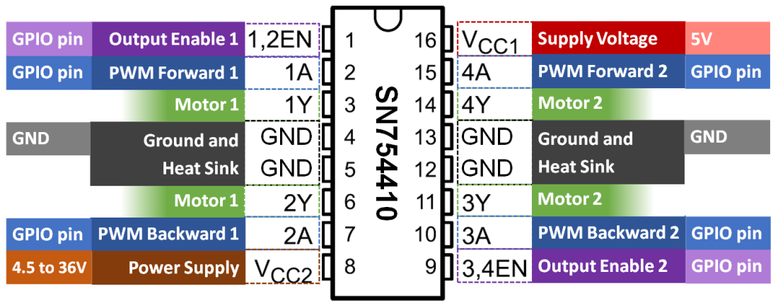
For a single motor, in addition to the 5V and GND pins, only 3 GPIO pins are required. Unlike the DAC with RC filters, a much lower PWM frequency can be used for the DC motor. Therefore, any 3 GPIO pins can be chosen since the software-implemented PWM at 100 Hz is sufficient.

The breadboard diagram illustrates the wiring for the DC motor control. For example, the Enable signal can be connected to GPIO16, while PWM Forward and PWM Backward could be connected respectively to GPIO17 and GPIO18. The forward speed of the motor is adjusted through the duty cycle of the PWM Forward signal. Correspondingly, the backward speed uses the PWM Backward signal.
Later on in this post, I will go over a Python Class where the three signals can be used to easily set the motor rotation (in an open-loop fashion for now).
L298 dual H-bridge motor speed controller (board)
Another option is to use an IC board which avoids the need of a breadboard and can therefore be used in a more permanent DIY setup. Most importantly, the reason I chose this particular board is that it has a fundamental difference in how the forward and backward rotation is implemented, when compared to the SN754410 chip.

While the wiring is very similar to the previous setup, by taking a closer look (based on the wiring color scheme), you will notice a different number of Enable and PWM signals. This board has 2 Enable signals and only 1 PWM signal. Rotation direction is now controlled with Enable Forward and Enable Backward, while speed is adjusted with a single PWM duty cycle.
Python Motor Class
Even though GPIO Zero has a Motor Class, the class is not ideal for applications where the motor output speed has to continuously transition between forward and backward rotation direction. The Motor Class implemented in the code below allows for that behavior. Additionally, by coding the class from scratch, we can see how the enable and PWM signals are used, as well as how to accommodate for the two types of wiring setup.
If you have been following along on my blog, in one of my previous posts (VS Code on Raspberry Pi) I encourage the creation of a folder dedicated to your Python modules. With that said, this code should be saved in a module named gpiozero_extended.py alongside utils.py in the /home/pi/python/modules folder on your Raspberry Pi. Also, the fully commented Class can be found on my GitHub page.
from gpiozero import DigitalOutputDevice, PWMOutputDevice


class Motor:

    def __init__(self, enable1=None, enable2=None, pwm1=None, pwm2=None):

        # Identifying motor driver type and assigning appropriate GPIO pins
        if pwm1 and pwm2:
            # Driver with 1 enable and 2 PWM inputs
            # Example: SN754410 quadruple half-H driver chip
            if not enable1:
                raise Exception('"enable1" pin is undefined.')
            self._dualpwm = True
            self._enable1 = DigitalOutputDevice(enable1)
            self._pwm1 = PWMOutputDevice(pwm1)
            self._pwm2 = PWMOutputDevice(pwm2)
        elif enable1 and enable2:
            # Driver with 2 enables and 1 PWM input
            # Example: L298 dual H-bridge motor speed controller board
            if not pwm1:
                raise Exception('"pwm1" pin is undefined.')
            self._dualpwm = False
            self._enable1 = DigitalOutputDevice(enable1)
            self._enable2 = DigitalOutputDevice(enable2)
            self._pwm1 = PWMOutputDevice(pwm1)
        else:
            raise Exception('Pin configuration is incorrect.')
        # Initializing output value
        self._value = 0

    def __del__(self):

        # Releasing GPIO pins
        if self._dualpwm:
            self._enable1.close()
            self._pwm1.close()
            self._pwm2.close()
        else:
            self._enable1.close()
            self._enable2.close()
            self._pwm1.close()

    @property
    def value(self):
        return self._value

    @value.setter
    def value(self, _):
        print('"value" is a read only attribute.')

    def set_output(self, output, brake=False):

        # Limiting output
        if output > 1:
            output = 1
        elif output < -1:
            output = -1
        # Forward rotation
        if output > 0:
            if self._dualpwm:
                self._enable1.on()
                self._pwm1.value = output
                self._pwm2.value = 0
            else:
                self._enable1.on()
                self._enable2.off()
                self._pwm1.value = output
        # Backward rotation
        elif output < 0:
            if self._dualpwm:
                self._enable1.on()
                self._pwm1.value = 0
                self._pwm2.value = -output
            else:
                self._enable1.off()
                self._enable2.on()
                self._pwm1.value = -output
        # Stop motor
        elif output == 0:
            if brake:
                if self._dualpwm:
                    self._enable1.off()
                    self._pwm1.value = 0
                    self._pwm2.value = 0
                else:
                    self._enable1.off()
                    self._enable2.off()
                    self._pwm1.value = 0
            else:
                if self._dualpwm:
                    self._enable1.on()
                    self._pwm1.value = 0
                    self._pwm2.value = 0
                else:
                    self._enable1.on()
                    self._enable2.on()
                    self._pwm1.value = 0
        # Updating output value property
        self._value = output
The following example creates a motor object and runs a sinusoidal excitation with an amplitude of 1 for one full period. If you execute the program, you will notice that the direction of the motor rotation changes as the sign of the sine wave changes.
# Importing modules and classes
import time
import numpy as np
from gpiozero_extended import Motor

# Assigning parameter values
T = 4  # Period of sine wave (s)
u0 = 1  # Motor output amplitude
tstop = 4  # Sine wave duration (s)
tsample = 0.01  # Sampling period for code execution (s)

# Creating motor object using GPIO pins 16, 17, and 18
# (using SN754410 quadruple half-H driver chip)
mymotor = Motor(enable1=16, pwm1=17, pwm2=18)

# Initializing current time stamp and starting clock
tprev = 0
tcurr = 0
tstart = time.perf_counter()

# Running motor sine wave output
print('Running code for', tstop, 'seconds ...')
while tcurr <= tstop:
    # Getting current time (s)
    tcurr = time.perf_counter() - tstart
    # Doing I/O every `tsample` seconds
    if (np.floor(tcurr/tsample) - np.floor(tprev/tsample)) == 1:
        # Assigning motor sinusoidal output using the current time stamp
        mymotor.set_output(u0 * np.sin((2*np.pi/T) * tcurr))
    # Updating previous time value
    tprev = tcurr

print('Done.')
# Stopping motor and releasing GPIO pins
mymotor.set_output(0, brake=True)
del mymotor
DC Motor Remarks
If you’re using a motor with an integrated gear box and try some low output values with the motor object, you’ll notice that there’s a dead band where there’s no speed response as the sign changes around small duty cycle values. That happens because it is the DC motor torque (not the angular velocity) that is proportional to the input current (or very simplistically the PWM duty cycle). For small duty cycle values, the torque is being used to overcome the friction losses in the motor bearings and the gear box before the output shaft starts to turn.
There are several low-budget small DC motors that can be purchased online, usually with a wide range of gear ratios for the same overall packaging constraints. There should be an output shaft speed / torque combination that meets your project requirements. Keep in mind that the SN74410 has a limit of 1 Ampère per driver, which might affect the output that can be achieved. Board controllers are generally rated at much higher currents (5 A and above). The power supply capability should also be taken into account, by the way.
Finally, as I mentioned at the top, a motor with an integrated encoder will become essential if we want to incorporate the angular position of the output shaft into the Motor Class. That will enable closed-loop control of the motor speed and/or angular position, making for a good automation example.

One thought on “H-Bridge and DC Motor with Raspberry Pi”